

Over the course of 8 1/2 years as a Mac user (and 20 1/2 years of owning an Apple of some kind) I’ve accumulated several computers, with as many as four operating at any one time. My current total is that number, plus a Playstation 2 with a network module making “five with Cat-5.” Only two are Airport-capable, and one of those two is the primary family machine, which already sits in the same room as the broadband router that connects everything to the Internet. The first-generation iMac 233, the Power Mac 7200/90, and the Playstation are either a wall or a floor apart from both the router and each other. Using a pure 802.11 wireless solution was clearly not going to be cost-effective, even with the price of access points and wireless routers dropping like stones. It was time to start running some cables and attaching connectors to leverage the built-in Ethernet of all those systems.
To lower the project price even further, I made the decision to eschew (at this point) putting in wall plates with Ethernet (RJ-45) jacks; instead I used the existing telephone or coaxial cable-satellite TV wall jacks and drilled a half-inch hole through which I could feed the networking cabling. For walls requiring penetration where no legacy wall plate existed, I purchased the least expensive wall plates I could find at the local home improvement store. These turned out to be the wall plates for the hard-wired round telephone connections, which cost less than a dollar each. Had blank wall plates been the cheapest, I would have drilled my own hole in them.
I already had a spool of Category-5 unshielded twisted pair (Cat-5 UTP for short) left over from an earlier wiring project at my previous home, so the next step was borrowing a termination kit for the 8-wire RJ-45 connectors which are the ubiquitous means to connect devices to each other. I had never actually made an RJ-45 connector before; my two prior houses were bought new and I did wire both with extra telephone, coaxial (cable TV), and security wiring before the drywall was mounted, but I had to subcontract the Ethernet termination work as part of a “builder option.” The person loaning me the crimping tool also donated a large package of the clear plastic RJ-45 connectors and said I could use as many as I needed. That turned out to be critical, as you will see.
One of the target machines was installed in a room adjacent to the router. I had a sufficiently long pre-made Cat-5 cable in stock, so adding that first machine to the network was as simple as punching a hole in an interior wall, mounting the round-hole wall plate mentioned above, and fishing the cable through.
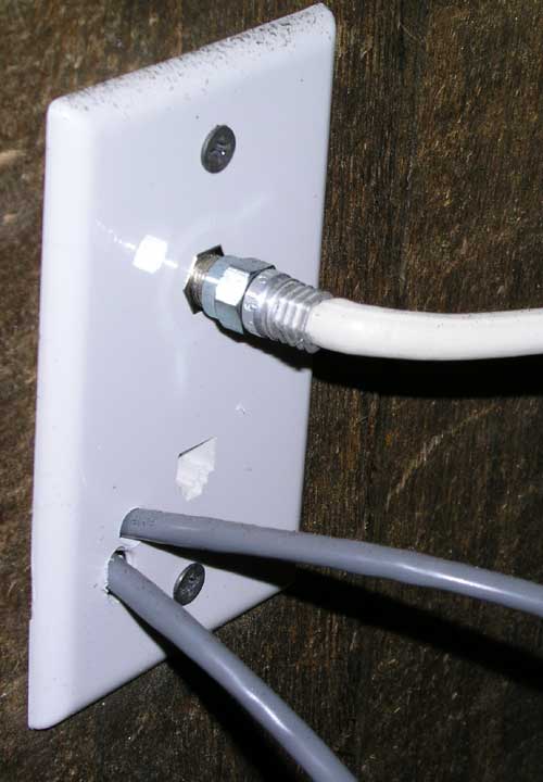
Fig. 1: Instead of installing separate RJ-45 jacks for each cable emanating from the router, the author modified the existing wallplates (by drilling holes through them) to allow the cables to simply "pass through."
The other two machines were installed in the room immediately below the router, so here begins the true odyssey. I determined that the easiest route between floors was inside the closet of the upstairs room, which conveniently sat mostly atop the unfinished laundry room. I drilled the extra hole in the telephone wall plate of the room with the cable modem (fig. 1), drilled another hole inside the closet through the drywall behind the wall plate, and then drilled the final hole through the floor of the closet, down into the laundry room (fig. 2). I put the second hole an inch above the floor, in an area normally covered by baseboard so I could easily hide it if I ever sell the house. The third hole was drilled as far in the corner of the closet as I could muster, making it essentially invisible except when standing inside the closet. With a significantly greater amount of effort, I imagine I could have avoided the second hole by drilling from below up through the hollow space in the wall above. However I had less than 8” of vertical clearance from below (fig. 3) so I would have had to buy or borrow more sophisticated tools than I owned. For me it was not worth the effort.
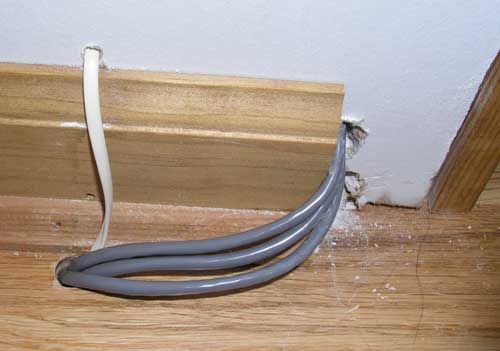
Fig. 2: On the opposite side of the wall shown in Fig. 1, two additional holes were drilled to allow access to the unfinished portion of the lower level. Since the holes are inside a closet, they are not noticeable to the casual observer.
Instead of precisely measuring the lengths of the cables needed to reach the two downstairs locations, I “guesstimated” and added 10% more length as a “fudge factor” (the latter technique being common in all the trades, I’ve been told). Since my arm span (the distance between my hands when stretched as far apart as possible) closely matches my height (six feet), I counted out two varying lengths and cut the cable at each point. With a helper, I could have also pulled the ‘runs’ in succession and made sure they were long enough before making the cuts; let’s just say my wife does not share my passion for technology (nor, after taking care of our three kids all day, my after-10 pm work schedule for this project.)
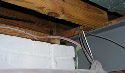
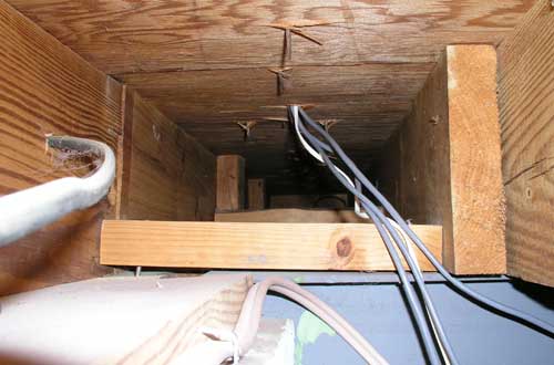
Fig. 3a, 3b: The holes drilled in the floor emerged in a hard-to-reach area of the unfinished area of the basement, requiring barbeque tongs to retrieve the wires once they were pushed through.
The first cable was cut at around 30 feet; the second at close to 75 feet because it had another wall to pass through and was destined for the far side of the downstairs recreation room. This will become significant, as you the reader will see.
Having never terminated Cat-5 before, I relied on the “sample connector” which was in the pouch with the RJ-45 crimping tool to determine the proper arrangement of the eight wires. I knew that only four were actually used, but that the common practice was to connect all eight because it is actually simpler to line everything up inside the connector if all the wire slots are filled. Looking at the side of the connector opposite the clip and checking left to right, here’s what I thought I saw:
Orange/white stripe
Orange
Blue/white stripe
Blue
Green/white stripe
Green
Brown/white stripe
Brown
Those of you experienced in the fabrication of EIA-213B connections know right away where this story is headed. I dutifully crimped this wire pattern on both ends of both cables, and was rewarded with immediate success when I tested the shorter cable by accessing the Internet and personal file sharing. However, the longer cable was only “half-working”; the “link” and “speed” lights on the router were showing the cable had a valid connection at 100mbps, but only inbound packets were making it through. Every packet headed back to the remote end resulted in a transmission error. I re-did both ends of this longer cable using the same wire pattern as before, and the result was the same. At this point I feared that one (or more) of the wires was damaged somewhere along the length of the cable, and I had a long troubleshooting session ahead of me. I tried two more sets of connectors with two different wire patterns to try to isolate the ‘bad wire’, but it made no difference. This is why it was invaluable to have so many extra connectors available.
It was then that I went back and looked at some of the other Cat-5 cables I have lying around the house. One of them only had the four ‘live’ wires in the connector, and clearly showed that pins 1-3 and 6 were the active ones. On my cable, 1 and 2 were the wholly- or partially-orange wires, but 3 was the blue/white wire and 6 was the solid green one. This arrangement worked fine for the 30’ cable, why not the longer one?
Here’s why: recall that 100Mb Ethernet requires unshielded twisted pair wiring. Although I knew that with CAT-5, the wires with shared colors were wrapped around each other in a helix for the length of the cable, I failed to grasp the importance of it. When wired correctly (which will be enumerated momentarily), the same data is passed down both the solid and striped wires of the same color. Because they twist around each other, they are far more resistant to both attenuation (loss of signal strength over distance) and electromagnetic noise (such as house electrical wiring and radio waves) than if only one of the wires passes data. Purists (or übergeeks) will care that while the two wires carry the same information, they are of opposite phases to make error correction a breeze; this is too far “in the weeds” for 90% of readers.
I also consulted an Internet resource on Cat-5 and found that the following pattern was one of the two approved arrangements.
Orange/white stripe
Orange
Green/white stripe
Blue
Blue/white stripe
Green
Brown/white stripe
Brown
In a nutshell, the green/white and blue/white were swapped in my initial cables, so that the data signal traveling in one direction was split between one of the blue pair wires and one of the green pair wires. The combination of attenuation and/or electromagnetic noise created a situation akin to trying to shout across a crowded, noisy auditorium and expecting to be understood. Frankly, I was lucky my first cable (wired the wrong way) worked at all; it greatly benefited from being short enough that the signal could still be discerned at the far end. Once I wired the connectors correctly, the longer cable worked flawlessly.
I came out of this experience far wiser, and with an Ethernet wired home, at a cost of less than $5 (for wall plates).
Craig Contardi is currently the Secretary of Washington Apple Pi. He is married, with three children between the ages of 4 and 8.